19 November, 2011

Petzl Myo XP repair

My first headlight was the Petzl Myo XP and I loved it from the beginning. Very well designed and build with little things to pick on.

I was pretty amazed when after 1 year of use my headlight broke down experiencing cable problems on the side where the cable enters the light head. Didn't thought much about it and put it all on a bad production sample, just returned the product to the store and got a brand new one instead. I've got mine from a local supplier, Himalaya, having luck on my side as there the guys are big and serious about their business with all interest in keeping a good name about the products they promote.

All was back on track again till 1 year after when this 2nd headlamp failed with same symptoms. This time I was more than intrigued and determined to get tot he bottom of it on my own.


There's nothing you can't do with the right tools so with a T6 torx it was all pieces on my worktable in no time. As I was anticipating, the good design from the outside was found inside as well. The LED chip is mounted on a separate PCB that has an extra aluminum radiator for efficient heat dissipation. Even more, a thermal probe is mounted on the heat-sink for thermal shutdown protection.
The LED chip looks like a Cree product but I might be mistaken. All looked fine with the solder points but with a multimeter I found my problem to be inside the cable. Only solution now was stripping it apart little by little.


Need I say my surprise when finding the inner conductors? I couldn't believe my eyes, finding the wires in such a bad shape for such a high overall quality product. It looks like the wires suffered severe aging problems from low temperature exposures, at least that's the only thing that makes sense to me. The isolation layer lost it's elastic properties and cracked all around in multiple places. One of them got more mechanical stress than the others and that's how the electrical link failed.

The only thing I could do in this case was to cut away the most exposed part of the cable and resolder it to the PCB. Of course it got shorter in the process, of course I didn't solve the problem, just the effect but for now it will have to do.

UPDATE: Another Petzl Myo XP repair

CoolLCD Super Clamp tweak


With my CoolLCD order I got 3 Super Clamps, little widgets that are priceless bargains for any photographer out there.

If there's not much I can say bad about the actual clamps, the included extender with 1/4" and 3/8" thread on the other hand is pretty poor design.

First, it lacks any rubber washer on the base of the threads. Second, it doesn't offer any firm grip area when you want to tighten or loosen the screw. And last, I tend to think the material is on the soft side as I noticed with one of the extenders that the 1/4" thread got bended.

At least I got rid of the first two problems with home made washers from a rubber carpet and a little lathe work to get that needed grip area.

I included a before and after picture (without the washers though).

17 August, 2011

CoolLCD products

Since my Zaganu project is already operational I am now looking at the photo side of the project. As I've said in the first post about Zaganu, I intend using this behemoth in aerial photography, and in order to do that I need of course to attach a digital camera to it, and also video a camera with live feed would help. The video camera's purpose is to get a better idea of how the machine is oriented during flight or hover relative to the subject that we want to picture.
 I got the video camera and AV transmitter from HobbyKing and I think it was quite a bargain at a little over 50$. The missing link in this chain was a portable monitor on which to view the live feed. In RC business they usually use video goggles for FPV (First Person View) experiences but this didn't suit my needs and that's partly because I also wanted this monitor for something else. I wanted to use it as a "director's screen" on my DSLR when it comes to shooting video.
 This portable monitor market is quite big and diverse now and it's not so easy to make up your mind. But since I wanted to go cheap on this one and avoid having to spend around 500$ for the monitor alone, I turned my attention to CoolLCD. I found them by google and at first I thought it must be a prank or something. Two weeks after and a lot of googling, my order was on the way.
 I knew it's not going to be high end quality or top features and I was quite afraid of the worse but boy was I wrong. All those good comments from their site weren't for nothing. From start I must say their before-order support is great and the time of delivery unbelievable.

I just got the chance to unwrap the products (as I bought quite a few stuff) and do a video while doing it. More infos will come later as I'll play with them and put them to work.

Till then, here it is:


11 April, 2011

Zăganu - 04 Trial times

Since spring time is here and I start to become to anxious about it, I decided to take a short cut and by-pass my DIY controller for a while and use the original arduino version. So I got an arduino nano from farnell and start putting it all together. The arduino board was pretty straight forward to connect and program. I used the latest MultiWii version (1_preter7) and carried on with further configs through the USB port and the GUI software.
Almost ready to fly

I'm not so sure about the center plate design so I improvised a lot, using cable ties and duct tape here and there. I didn't want to let everything loose from the start so based on an idea I found on rcgroups.com, I build something like a test bench. It helps with keeping it on the ground while allowing it some degree of free movement.


 First try was quite scary because the sensors weren't aligned with the motors and the tunning loop got crazy. Rest of the tries weren't that scary but not successful either. Using the GUI I can see the accelerometers getting correct readings, even though they turn quite noisy once the motors start to spin, the gyro signals are sadly confusing. The magnitude on Y axis is roughly twice as low as on the X axis for the same amount of movement, if judging from the plot even though the numbers seem to match if monitored on the digital read out. Didn't figure out yet if it's a plot issue or a real sensor issue. Also have some troubles  understanding the logic behind the trimming procedure or the software functionality but that can be solved with some reverse engineering on the code.

Hope to get an actual flight till next post but until then, the work must go on

23 March, 2011

E-Boda Stylance 2302

 
 http://www.e-boda.ro/televizor-led-full-hd-1080p-23-e-boda-stylance-led-2302.html

Since our good old CRT kitchen TV was failing more often than I had time to send it to the service I decided something needed to be done and take a step forward and buy a new one. Wasn't keen on spending much on it but didn't want to stick with the dying CRT technology either.

So while surfing the net I came across this E-Boda model that promised to be a best price acquisition. It was just big enough for the space I had available, LED technology promising an ultra low power consumption, made by a Romanian firm if wanting to be a little nationalist about it and the good price as I've mentioned earlier.

Got the TV from emag.ro, a big online store here in Romania. They were fast about it and I had it delivered in no time. Got home keen on unpacking and testing it out but that's when disappointment began.

First of all, the table top stand just plugs in into the unit with no screw lock or other locking mechanism which makes the thing pretty unstable if subjected to touching or any physical interaction. Another thing that bugged me before even plugging it in was the power cord. It's not a normal removable standard type but a permanently fixed  cord. Well, if the downsides would have stopped here all would be OK because I knew I can't expect top quality from a best buy.

One of the big upsets came from the response time. It takes as long as a lamp TV to start and switching channels isn't any faster either. Part of the blame for the slow start up is caused by a 1-2 seconds screen with a big E-Boda logo.

The second big upset was with the sound. Sound quality is just plain awful, with no trace of depth or bass. No matter how you play with the sound options from the menu things don't look any better.

Image quality isn't that good either but that might have been a place I was expecting a little compromise.

All in all, I was so disappointed by the TV that I returned it as fast as I could and didn't even take the time to get some photos for this post. The guys from emag.ro were quick as always and now I'm waiting for another cheaper but higher hopes model. I'll be back with comments when I'll get it.

08 March, 2011

Zăganu - 03 Still alive

Finally back from abroad. Good news is that the project is still alive, during those long cold Russian winter nights I had plenty of time to dive deep into the software side of things. Because it passed some time since I last worked with embedded devices, it took me a little to get back in shape and get familiar with TI's platform. I got a hold of CCS and the Luminary Micro platform which even though is way over the needs of the project is definitely lots of fun to play with.

Starting from the info's from starlino.com I got up and running a 6 DOF IMU. It still needs some tunning but all looks good so far.

I also did some rethinking of the hardware and replaced the FR4 center plate with a 2mm thick 160x160 aluminum plate which is lot easier but stiffer. For now i gave up on the octo configuration since I'm still far away from that point so the center plate is square as I've said and the arms got closer together to shrink things a little.

Got to do some power tests and at full throttle with the frame "bolted down" I only got 8A per motor which was enough to give the frame lift off capability but only half of what the motors can put out so I'm considering bigger props.

08 February, 2011

Zăganu - 02 Somewhere in between

OK, so most of the materials arrived, I'm almost done with the mechanics but way behind with the software and worst of all I'll have to stop for a couple of weeks because a long mountain trip and a longer foreign trip are coming next. But till then, let me put it down with the progress so far.


 You have in the picture above a view over the base plate and an equipped arm. The plate is 2mm thick FR-4 at a hefty 360gr but I plan to loose some weight by drilling some holes between the arms. As you can see it's octo shaped for the final idea but for now only four arms will be on for easier (and cheaper) operation.


 The arms came out at around 40cm long. Since all I could find locally were 9'' GWS tri-blades I chose to mount them closer to the center plate. This gives a welcomed protection to the propellers on forced landing and I guess it also helps with the dynamics of motion a little. The motors are labeled BL FC2835-10T at 830Kv and at aprox 10V they gave around 120W of power. Too bad I couldn't measure the actual thrust as I fear it might not be enough for the total weight but I'll work on that once I'll be back.

 ESC's are HobbyKing's BlueSeries 30 amps model. I am quite amazed with the quality of these little things and I'm talking here about all the electronics involved in the RC business. It's true I can't do any comparison since I'm a newb in the field.

 Together with the essential  parts for the build I also ordered lots of extra gadgets, to many actually if I think back about it. Well, anyway.. time is short and I'll have to talk some other time about them. I'm still missing the batteries and the charger for them but that's the thing I'll take care first once I'm back at work.


This is what's left from a Wii Motion Plus and a Nunchuk after I hacked them. I can't find any possible use for the joystick and the two buttons but I didn't have the heart to cut them off either.. u never know when they might come in handy. The sensors do their job as expected, communication is working alright but I'm having tons of problems with the MCU and it's IDE. No matter how hard I try to blame myself for all the problems I encounter it keeps pointing out that there's something fishy out there and I can only assume it's because of an early silicon revision of the chip but I didn't have time to dig into it too deep. All in all I hope I'll get over it because I'm eager to get things moving sooner, especially now that good weather's coming up.

That's about it for now, have to run finish my pack and get some sleep also..

30 January, 2011

Zăganu - 01 Introduction

OK, so after some words in the previous post about all this project wants to be it's time to get into the serious stuff. There are so many things into such a major project that it's hard to put things in order. Spent my last two weeks just surfing the net and trying to assimilate as much info in the field as I could since I'm a newb in all this RC hobby.

Except the documenting phase there's also a lot of acquisitions needed, from the Tx/Rx system, batteries, motors, ESCs, BECs, frame and so on. From all these I'm sure about this:
  • I'll make the frame DIY style, using 10x12x1 rectangular aluminum hollow tube for the motor arms and carbon fiber or FR-4 plate for the center part
  • I'll go the cheap way with the motors, propellers and ESCs since they are prone to destruction during trials. I've already ordered ESCs from the giant HobbyKing, the props and motors I intend acquiring from local suppliers
  • For the flight controller I took the MultiWii path with some modifications. I acquired the original Wii Motion Plus and Nunchuk controllers as to avoid any problems with the cheap replicas. I'll try implementing the actual controller on a LM3S3748 development board I already had. If that doesn't work out then I'll switch to the Arduino approach with the software already available
  • for the Rx/Tx system I went for Hitec Aurora 9 which is quite a lot over average but it should make my life a lot easier with all it's bells and bells and whistles. 
 As for some quick links on the subject, here are a few that I really consider essential:


So now I've sketched the frame and it's as ready as it can be till I get the rest of the components. I've also hacked the Wii controllers and successfully communicated with them over I2C. That's about it for now, I'll come back with some pictures and details on my work in the next post.

27 January, 2011

Zăganu - the start of a dream

According to wiki, Zăganu was a species of big eagle that once lived in the mountains of Romania. But I'm not going to talk about this here. Zăganu is just a name i took and gave to my latest project and the only thing that has in common to the bird is it's the flying abilities and the big size.

So.. to cut it short and get on topic, I'm actually talking about a RC multirotor helicopter model. The idea ain't new, neither to myself as I've pondered on it for some time now, and neither to the rest of the world, since there are many projects out there on the subject. Most of them started in the RC model community but the apparent simplicity of the idea made it a wildfire through every hobbyist of one kind or another.

What really got my attention was the photographic opportunity that these machines offer. I first got the idea seeing some BTS movies somewhere on the net with video cameras mounted on RC helicopters. The problem with classic helicopters though is that they're quite exclusivistic in the sense that the hardware involved is quite complicated with lots of moving parts on one side and things that need to be fine tunned on the other, and besides all this, in order to fly a heli you do need some serious skills and practice. The quick way out of this are the multirotor helicopters where all the fancy mechanics and serious skills move to more than one rotor and some sort of controller electronic board.

Most of the multirotor designs involve tri or quad motor designs as they are somewhat simpler and cheaper to build, but when you have and expensive and hefty payload like a DSLR camera then a hex or octo design is best as it is a more stable platform. Since a DSLR is my ultimate goal for such a flying machine I choose starting with a quad design for testing and tuning of the controller and then expanding to octo for the final "product". I'll stop here for now and get back with details as the work continues.

10 January, 2011

Nixies and Mitino Radio Market

Well, some of you might not even know what the tittle is all about so let me put some references about nixies. Pretty cool, right? I was always found about that electric shine. The problem is that nixies are history and the only way you can put your hands on something like this is if you salvage it from old equipment or buy it from fairs or even the internet.

Mitino Radio Market
Nixies recovered from an old equipment
Had a few nixies back home donated by a friend of mine but I wouldn't mind getting some more. In a business trip last year I strolled through what I later found out was the famous Mitino Radio Market. I was on the run looking for a megohmeter and some other tools but I couldn't help not noticing one store's showcase. It was packed with nixies, all shapes and sizes. Sadly though I didn't have time for it and the shop was closed any way. After my trip was done, on the way back home, having some extra hours between flights I hopped on the Aeroexpress, changed it for the sub, added a hefty part of walking and I was back roaming the Market. The place is awesome, a lot more shops than I first saw. Anything you can imagine in the field of electronics is there, from car audio and GPS units, to motor rewinding shops, custom battery pack manufacture shops and electronics antiquity shops.

 I went in the shop where I first saw the nixies and this time it was opened. The prices for a piece were insignificant and took quite a few. Bargaining with the seller wasn't a problem since he was patient with me and my flourish. Left the shop with literally a bag full of nixies and VFDs for no more than 15$ or so, quite a bargain I'd say.

Once I was back home, didn't have the time for them so I postponed a close eye review. Now the time came so here are some close-ups:


 The biggest VFD of them all was what looked like a clock display. Sadly it can't be used because the envelope's evacuation tubeglass was broken either before I bough it or while I transported back home. Once the vacuum escapes the envelope it's no longer a V in the VFD so it will definitely not work, hihi.. Another piece for my little electronics history museum.

VFD with evacuation tubeglass broken (right side)
Even though brand new these little wonders are ancient stuff but with a little Google on the search, a little Google on the translation, I got the tech infos I needed in no time. Russian hobbyist keep pretty good records of all mother Russia had to offer in it's glory days.
Now all I have to do is develop a HV supply, draw out a schematic, figure out a purpose and above all find the time to do it all. So.. back in line on the long list of not_have_time projects of mine.

09 January, 2011

Lambency 77mm White Balance Lens Cap

Recently it keeps bugging me about all this color management thing when it comes to digital photography work-flow. Back in the old days, everything was straightforward and hard codded, now in the digital era, everything is virtual and relative.
What I mean here is that unless you take special measures, by default, taking and viewing an image won't show you anything else other than a bunch of assumptions. The camera you took the photo is assuming how bright and what color tones the scene must have had, the monitor assumes what that picture file should be displayed as and if you print it, then the printer takes it's own assumptions.
To cut it short and get on topic,  preoccupied by all these assumptions and having problems with some inconsistent results, I tried to put some order into things and started with the most basic step you can take, the white balance.

The theory is pretty simple. Most respectable camera out there offers the option to set a custom white balance level based on a sample photo taken of a gray card or alike. Since I wasn't so found of the gray card idea, I choose the alternative, a white balance lens cap. Basically it's a lens cap that has an extra transmissive window in it that the camera can picture and consider for the custom white balance.

My fault was to grab whatever came first and trust the retailer, so I stopped on a so called Lambency 77mm White Balance Lens Cap. "so called" because after unwrapping it I couldn't find any reference about Lambency producer on the package, nor any other producer for that matters. Chose the 77mm because it would suit two of my four lenses.


The quality of the product is plain modest, cheep plastic and bad taste golden ring around the window. The fixing mechanism on the lens is the same as that of Nikon lenses. Took same test shots around the house and it did correct my incandescent light fairly well. Must be noted that in order to get the test shot with the cap on you need to set the lens on manual focus.  


The worst complain about this product is that it broke the very next day after I got it. While being on the camera in my backpack, the translucent dome came off. It turned out the locking mechanism was poorly designed and it broke with no way to put the dome back other than glue it back with a plastic hot glue gun. It's not a fix that will solve the problem for good since it's prone to failure because of the dome design that sticks out.

Conclusions:  attention, attention, attention.. Not to jump head first next time. I'm not sure how much I'll use this product from now on since I lost my trust in it and I already plan on getting a more reliable color checker board.

03 January, 2011

NiteRider Pro 1400 LED


NiteRider Pro 1400 LED
UPDATE: NiteRider Pro 1400 LED is now replaced by NiteRider Pro 3600 series

Just before the winter holidays started my latest obsession was finally in my hands, muhaha!! Yes, it's the new NiteRider Pro 1400LED bike headlight. Ever since I've seen it while surfing on Amazon I knew I must have it. Awesome specs, good reviews and huge potential to be the ultimate light source for all my outdoor activities: biking, caving, mountaineering and even photography.

So now that the holidays are over and I had the chance to put it to test in all the above mentioned activities, I can sit down a little and tell you all a little about this amazing product.

NiteRider Pro 1400 LED box back

NiteRider Pro 1400 LED box front
Starting with unpacking.. As I already knew from the reviews I read on the net the light came in a pouch with everything packed in really tight. So tight that once you get all the parts out, it's hard to put them back together to fit the pouch.

NiteRider Pro 1400 LED storage pouch

NiteRider Pro 1400 LED unpacked
Together with the light I also got the NiteRider Explorer Headband which is needed for using the light as a headlight in mountaineering or if biking without a helmet. The headband is wide enough to handle the 200 gr weight of the light head and offers 4 plastic hooks to aid cable routing to the battery pack. Wearing it I did get a little bothered by the head pressure caused by the light head support pressing. I guess more padding would have been needed but it's something you get used to.

NiteRider Pro 1400 LED headband

NiteRider Pro 1400 LED headband wrapped
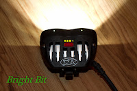
First thing that stroked me after looking at the light head was the fact that it didn't resemble the picture on NiteRider's website. That's because the picture there is actually of a Pro 1200 light system. The difference between the previous Pro 1200 and the current Pro 1400, besides the actual light output, is the presence of two light pipes, one for each reflector. You can see them in the first picture as two small dots. Their purpose is mainly when using the light on a bike, to show you which reflector is turned on. The actual LEDs inside each reflector are Cree XLamp MC-E.

NiteRider Pro 1400 LED light head turned on

NiteRider Pro 1400 LED light head


Moving on with the close eye inspection, I checked the cables and the connectors. The cable is very thick and rugged and the connectors well build. They are trapezoidal in shape with a flat matching key, they lock securely and offer quite good water proofness. The only problem that i could see is extra caution needed when connectors are unplugged/plugged in dirt/wet filled environments.
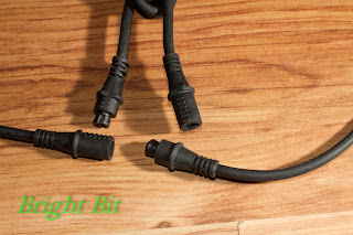

NiteRider Pro 1400 LED connectors

The battery pack is the biggest and heaviest part of the system. That's usually overcame by fixing it on the bike frame or caring it in the backpack, keeping it in a pocket is very uncomfortable. Quality is great, rubber pad for fixed mounting on the bike frame with Velcro straps that can easily be removed if you want to gain weight and space in non-bike activities. I wanted a little more info about battery pack maintenance so here are the producers recommendations:
When charging the battery, it should be done inside at room temperature. The batteries should not be charged below or above certain temperatures. There is a safety circuit that will shut off the charge if it is in such temperatures. For long term storage, it is best to store the battery at about 40% charge. If you are storing the battery for longer than a couple of months, it is best to store it at 50% then, about once every six to eight weeks, fully discharge, fully charge then discharge to about 50% for storage again. 


NiteRider Pro 1400 LED battery mounted

NiteRider Pro 1400 LED battery and cradle
The helmet mount will only work with vented helmets. It uses two straps that need 4 frontal vents in the helmet to get a fix. It won't work on most full helmets or a climbing helmet like my Petzl Elios, since the need of the Explorer Headband.


NiteRider Pro 1400 LED helmet mount

The handlebar mount is pretty straight forward and easy to use. The material is plastic and not metal like I think i read on a website. Just in case you need it, it comes with an extra rubber pad and an Allen key.

NiteRider Pro 1400 LED handlebar mount

The unit also comes in with what one can call a docking station since it's more than just a charger. Besides the power jack and the battery cradle, the unit also has an mini USB port and a connector to plug in the light head. You do this to program the light head with custom user light patterns. One thing I don't like about the docking station is the empty plastic case feeling. I've seen one unit opened somewhere on the web and it's a certain fact the unit is not the smallest it could be and that is really important when traveling.
The great thing about the power adapter is that it has universal input (100-240V/50-60Hz) so you can use it anywhere and the voltage output is 12V which means you can use a car plug adapter to power the docking station when on the move. A diode or two might be needed to create some voltage drop and get a true 12V output but that's something left to be seen.

NiteRider Pro 1400 LED charger bay


NiteRider Pro 1400 LED power adapter


Besides all these hardware aspects there's also the software side. The unit has 1 factory program with 3 light levels and 1 flash pattern and 4 user configurable programs with at most 6 light levels combinations and 6 flash patterns per program. That sounds like a lot of fun when you first think of it but at least for me it turned out to be more than I needed so I ended up using only 4 light levels and 3 flash patterns for 3 of the programs.
In the flash window you can even set a custom flash pattern with 0.05-1s on/off time. This pattern is shared between programs so only one given custom flash pattern can be used at any given time on the unit. Also about flash patterns, even though you can set 6 patterns per program, there are only 5 distinct options to choose from so you either use the same pattern on two slots ore never use one slot.. that's a little awkward right? Maybe a second custom flash pattern should be there, right you guys from NiteRider?
One thing worth noting even if it's pretty much irrelevant is that on high speed flash patterns (like 0.05 on with 0.05 off) the light head's on-board controller doesn't keep up the count and lags a little from time to time.
The software that does all these is great but could have been better still. I'm not a fan at all for the applications with custom skins like this one and I don't understand why the Light window layout is one way while the Flash window layout, even though houses the same 6 settings style, is the opposite. Maybe I'm too fastidious..

Mods and tweaks
During prolonged bike tours in the countryside I considered some anti theft measures like replacing the battery pack's Velcro straps with plastic cable ties and replacing the "user friendly" screw and wing nut on the handlebar mount with an Allen head screw and a washer.
When I installed the Universal Handlebar Mount I noticed that the light head fixture wasn't adjustable like the helmet or head mounts. This meant that vertical adjustment of the light head had to be done by unscrewing and then tightening back the whole handlebar mount which is totally uncool. Salvation came from the helmet mount from which I took the light head support and switched it with the one on the handlebar mount. It's not a perfect switch since the systems are a little bit different but it can be done with no intrusive maneuvers in no time.


Official documentation
Prior to getting the real deal, the one thing that really bugged me was that the user manual on the NiteRider's web site didn't work. Hope I'm not breaking any rules but here is the scanned documentation that came with the unit.


Conclusions
As I've said in the beginning, these holidays i had the chance to give the unit a spin in all sort of activities. Used it in the cold, in the warm, when dry, when wet, low beam, high beam.. you name it.
First things first so I'll start with biking. Handlebar mounting wasn't a big thing, finding room for the battery pack was. The frame's down tube was already busy with the water bottle support that housed the AirZound Bike Horn so I had to squeeze the battery pack above it really tight. Since it's winter here I only had the chance for a quick 20 km city and surrounding trip. Light output is definitely enough for every need you can possibly have while riding and it's definitely more than you need within city limits.
The most annoying thing here is that you don't have enough control over the flash output. By default it is 700 lm on the flood reflector and you can't do anything about it. Why use the flood reflector? beats me cause it's definitely not something that you want to do with a 700 lm light source in traffic, where auto drivers freeze into panic when they see it but might just as well stop and beat the hell out of you.

While on the mountain I used the unit as a headlight. I tried using direct connection of the light head to the battery pack with the pack placed in my backpack's top pocket but it was to short so I had to add the extra extension. It put to shame my now discontinued Petzl Myo XP headlight and on paper it's far beyond the Petzl Ultra even though I didn't have the chance to see them side by side. For both biking and mountaineering most of the times I used 150 lm of spot light, adding extra only when needed.

I also had the chance to explore an old mining tunnel which was the only case when I felt flood light was better than spot. Having such a great light in  total darkness is a blessing for taking photos as it helps you find subjects to photograph, helps the camera auto-focus and can even be used as main light if no flash is at hand.
One thing that got me a little worried was the fact that while in the tunnel I actually heard the buzz coming from the inverter driving the LED's in the light head. When these switching power supply commutation noises can be heard it usually means somethings shaky inside, a coil or transformer not properly tightened. The noise disappeared once I was out the tunnel and haven't heard it since so it might have been a combination of factors like temperature and moisture (since the unit is not rated completely water proof).

All and all, the most important thing that must be kept in mind when dealing with this unit is the company's motto "Technical Lighting Systems". It is intended for off-rode night bike trips but it's definitely not worth the money if used just for that. You have a lot of light output, battery power and build quality but you loose something in the way whenever you turn sideways from it's main purpose.
Within city limits it's to big and heavy to use, it draws a lot of attention and changing from lighting to flash is not something that can be done easily while riding. That's why I won't give up the old Trelock LS330 which is perfect for the job.
On the mountain is just great on off-track trips to help you find your way into the night. You can spot tracks and signs that are hundred or thousands meters away which sometimes is a real life saver.

Am I happy with the purchase? Definitely yes! Could it be better? Definitely yes! Would I buy it again? I'm not sure..